


Новое поступление

VS1053 VS1053B стерео аудио mp3-плеер щит записи декодирования макетная плата модуль со

Yahboom Programmable Intelligent Micro: bit Building Block Balance Robot Car With APP Remote Control | Компьютеры и офис
US $50.64

isolated RS485 data acquisition module 8RO 8 Road relay output Modbus RTU communication for Signal control | Компьютеры и офис
4 342,59 руб.

C1FB 12 в мощный любительский радиоприемник 40 м CW короткий волны QRP
1 046,42 руб.

Макетная плата Waveshare STM32 STM32F407IGT6 USB HS/FS Ethernet NandFlash JTAG/SWD LCD для UART |
20 126,74 руб.

MQ-7 Module Carbon Monoxide Gas Sensor Detection Alarm MQ7 For Arduino | Компьютеры и офис

V4.1 Stereo BK3254 Bluetooth Module Dual 3W Amplifier Board FM Radio/TF Card/U Disk/USB to TTL | Компьютеры и офис
Характеристики
Open32F0-D Package B=ST original STM32F0DISCOVERY STM32F0 Cortex-M0 STM32F051 MCU STM 32 Board+2.2inch 320x240 Touch LCD+11 Acc |
История изменения цены
*Текущая стоимость уже могла изменится. Что бы узнать актуальную цену и проверить наличие товара, нажмите "Добавить в корзину"
| Месяц | Минимальная цена | Макс. стоимость | Цена |
|---|---|---|---|
| Mar-18-2026 | 0.31 руб. | 0.83 руб. | 0 руб. |
| Feb-18-2026 | 0.84 руб. | 0.4 руб. | 0 руб. |
| Jan-18-2026 | 0.62 руб. | 0.25 руб. | 0 руб. |
| Dec-18-2025 | 0.68 руб. | 0.40 руб. | 0 руб. |
| Nov-18-2025 | 0.43 руб. | 0.61 руб. | 0 руб. |
| Oct-18-2025 | 0.49 руб. | 0.64 руб. | 0 руб. |
| Sep-18-2025 | 0.13 руб. | 0.62 руб. | 0 руб. |
| Aug-18-2025 | 0.33 руб. | 0.66 руб. | 0 руб. |
| Jul-18-2025 | 0.52 руб. | 0.35 руб. | 0 руб. |
Описание товара


STM32 Board STM32F051R8T6 Cortex-M0 STM32 Development Board With STM32F0DISCOVERY Kit+2.2inch Touch LCD+9 Modules+Free Shipping
STM32 development board designed for the ST official tool STM32F0DISCOVERY, and integrates various standard interfaces, pretty easy for peripheral expansions.

Overview
Open32F0-D is an STM32 development board designed for the ST official tool STM32F0DISCOVERY, which features the STM32F051R8T6microcontroller onboard.
The Open32F0-D supports further expansion with various optional accessory boards for specific application. The modular and open design makes it the ideal for starting application development with STM32F0 series microcontrollers.
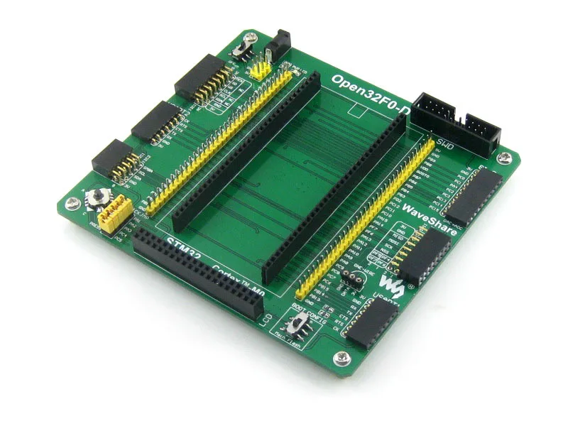
What's on the mother board

- STM32F0DISCOVERY socket: for easily connecting the STM32F0DISCOVERY
- 8I/Os + DAC + ADC interface: for connecting accessory boards such buttons, motors, AD/DA module etc.
- USART2 interface: easily connects to RS232, RS485, USB TO 232, etc.
- SPI1 / SPI2 interface:easily connects to SPI peripherals such as DataFlash (AT45DBxx), SD card, MP3 module, etc.
- LCD connector: for connecting touch screen LCD
- USART1 interface: easily connects to RS232, RS485, USB TO 232, etc.
- I2C1 / I2C2 interface: easily connects to I2C peripherals such as I/O expander (PCF8574), FRAM (FM24CLxx), etc.
- I2S / I2C1 interface: easily connects to I2S peripherals such as audio module, etc.
- ONE-WIRE interface: easily connects to ONE-WIRE devices (TO-92 package), such as temperature sensor (DS18B20), electronic registration number (DS2401), etc.
- 5V/3.3V power input/output: usually used as power output, also common-grounding with other user board
- 5V DC jack
- MCU pins connector: all the MCU I/O ports are accessible on expansion connectors for further expansion
- SWD interface: for debugging/programming
- Joystick jumper
- short the jumper to connect the joystick to default I/Os used in example code
- open the jumper to connect the joystick to custom I/Os via jumper wires
- Boot mode switch: for configuring BOOT0 pin
- Power switch
- Power indicator
- Joystick: five positions
What's on the STM32F0DISCOVERY

- STM32F051R8T6 microcontroller featuring 64 KB Flash, 8 KB RAM in an LQFP64 package
- On-board ST-LINK/V2 with selection mode switch to use the kit as a standalone ST-LINK/V2 (with SWD connector for programming and debugging)
- Board power supply: through USB bus or from an external 5 V supply voltage
- External application power supply: 3 V and 5 V
- Four LEDs:
- LD1 (red) for 3.3 V power on
- LD2 (red/green) for USB communication
- LD3 (green) for PC9 output
- LD4 (blue) for PC8 output
- Two push buttons (user and reset)
- Extension header for all LQFP64 I/Os for quick connection to prototyping board and easy probing
- An additional board is provided which can be connected to the extension connector for even easier prototyping and probing.
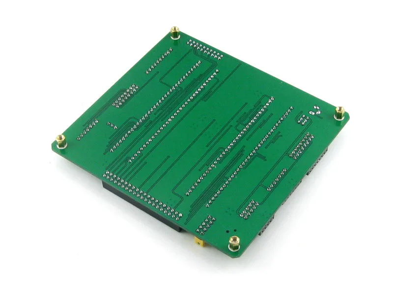
Photos

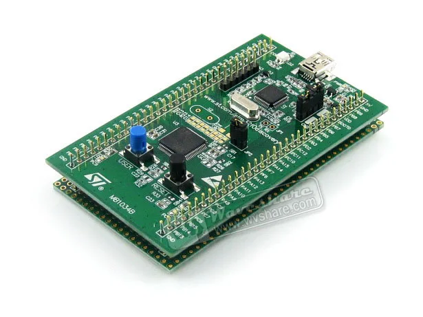
Open32F0-D development board

Open32F0-D development board back view

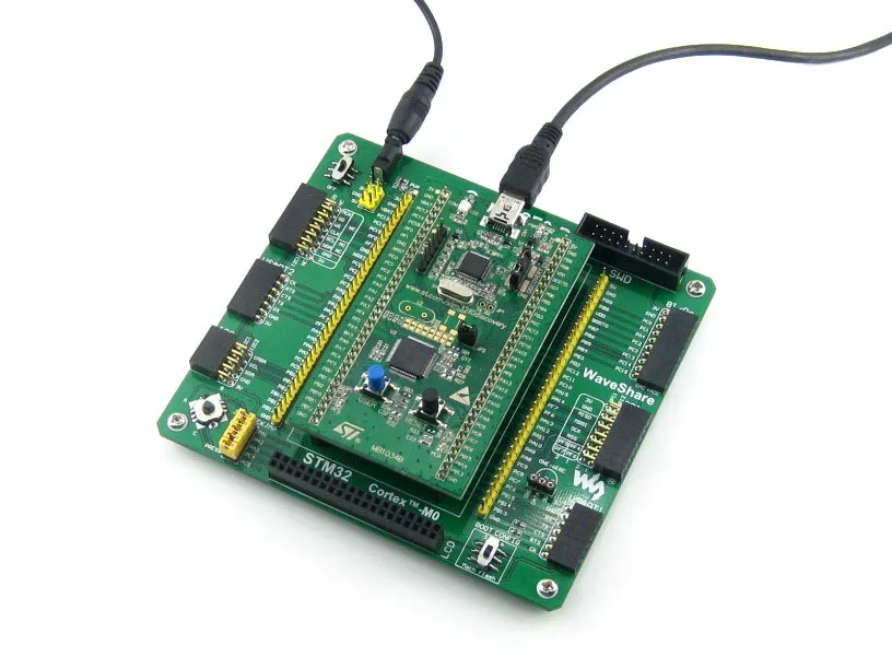
Open32F0-D Programming
Connecting to various peripherals

STM32 Cortex-M3 MCU board

STM32 Cortex-M3 MCU board

STM32 Cortex-M3 MCU board

STM32 Cortex-M3 MCU board

Connecting to RS232 Board

Connecting to RS485 Board

Connecting to USB UART Board

Connecting to 8 Push Buttons

Connecting to 5 IO Keypad

Connecting to AD Keypad

Test Board on the AD/DA port

Connecting to FRAM Board

Multi I2C peripheral Module connected to the I2C bus

Connecting to DataFlash Board

Connecting to UDA1380 Board

Connecting to VS1003B MP3 Board

Connecting to NRF24L01 RF Board

Connecting to Micro SD Storage Board

Connecting to any accessory board you need
Note:
The STM32F0DISCOVERY integrates ST-LINK/V2 for programming/debugging (SWD only).
SWD interfaces
The figure below show the header pinout of SWD interface
Figure 1. SWD Header Pinout
Development Resources
The User Guide CD includes development resources listed as follows:
- Related software (KEIL etc.)
- Demo code (examples in C, μC/OS-II)
- Schematic (PDF)
- STM32 development documentations (Datasheet etc.)
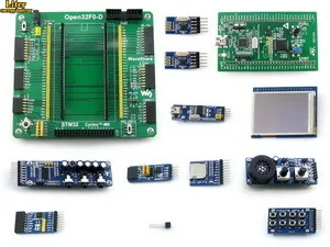
Package Contains
The "Standard Package" and "Accessory Boards Package" below are included.
Standard Package
- Open32F0-D mother board x 1
- USB type A plug to mini-B plug cable x 1
- 4-pin wire x 2
- 2-pin wire x 2
- USB power cable x 1
- User Guide CD x 1
 2
2  3
3  4
4  5
5  6
6 
Accessory Boards Package
- STM32F0DISCOVERY x 1
- 2.2inch 320x240 Touch LCD (A) x 1
- Micro SD Storage Board x 1
- FM24CLXX FRAM Board x 1
- UDA1380 Board x 1
- NRF24L01 RF Board (B) 2pcs x 1
- Analog Test Board x 1
- PL2303 USB UART Board (mini) x 1
- AT45DBXX DataFlash Board x 1
- 8 Push Buttons x 1
- DS18B20 x 1
 2
2  3
3  4
4  5
5  6
6  7
7  8
8  9
9  10
10  11
11 
Смотрите так же другие товары: